Physical Address
304 North Cardinal St.
Dorchester Center, MA 02124
Physical Address
304 North Cardinal St.
Dorchester Center, MA 02124

OSHA cited 730 companies for energy control procedure violations last year. That’s not a typo. Seven hundred thirty. More than any other lockout/tagout subsection.
The kicker? Most of those companies had procedures. They just had the wrong kind.
An energy control procedure template that passes audits looks nothing like the generic forms you download from safety supply websites. Those templates check a box. They don’t protect workers. And osha knows the difference.
I’ve reviewed hundreds of energy control procedures over 20 years. The ones that fail audits share the same problem: they’re written for “equipment” instead of for that specific hydraulic press on Line 3.
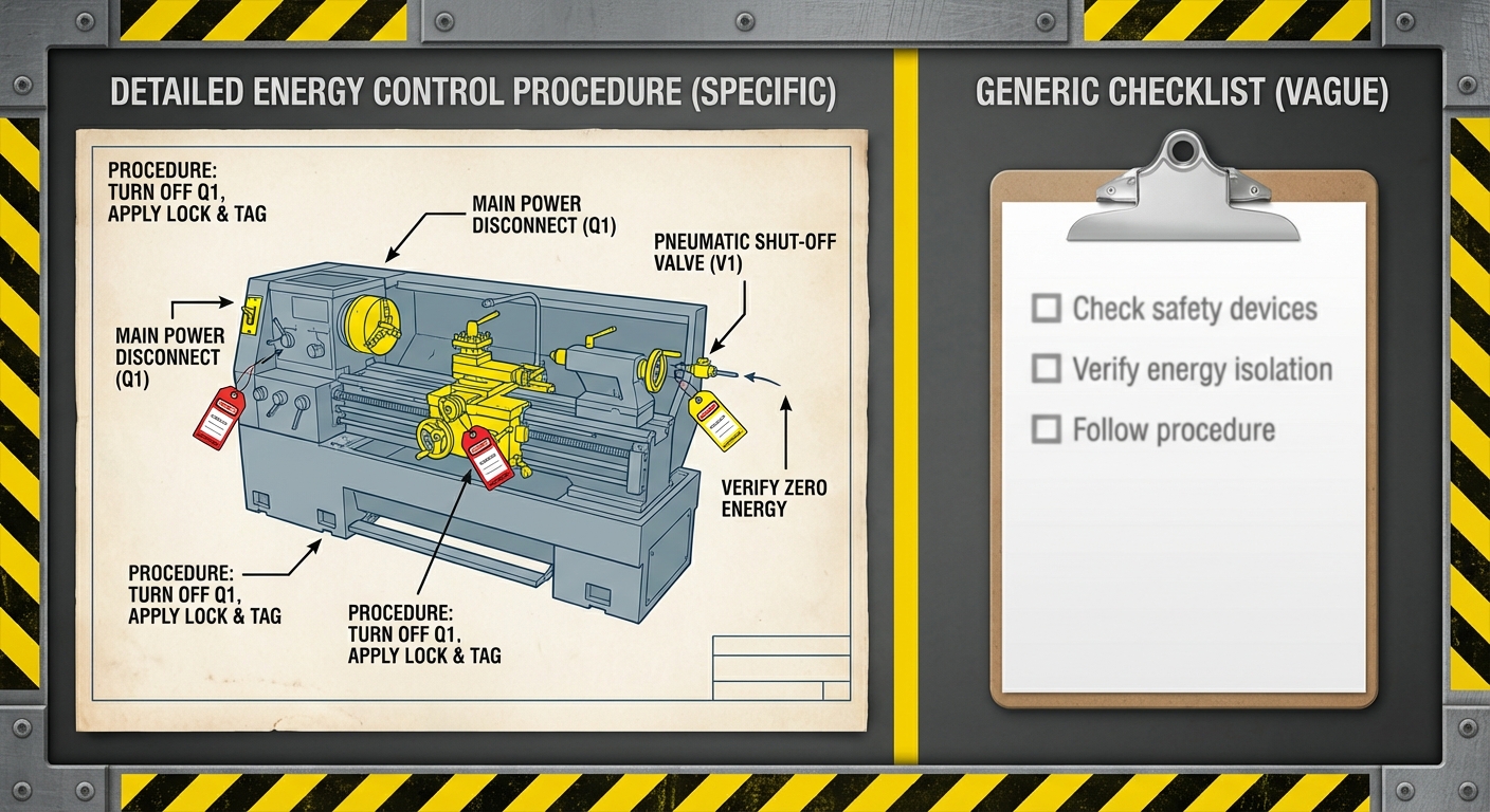
An energy control procedure is a machine-specific written document that details the exact steps for shutting down, isolating, blocking, and verifying zero energy state before servicing. Not a generic checklist. Not a one-page form. A procedure written for that machine.
“Procedures shall be developed, documented and utilized for the control of potentially hazardous energy when employees are engaged in the activities covered by this section.”
— 29 CFR 1910.147(c)(4)(i)
Shop Floor Translation: You need a written procedure for EVERY piece of equipment that requires lockout/tagout. “Every piece” means the CNC lathe gets its own procedure. The conveyor system gets its own procedure. The packaging machine gets its own procedure. One generic form covering “all equipment” fails the audit before the inspector finishes reading page one.
The regulation spells out exactly what each procedure must contain. Miss any of these elements and you’ve got a citation waiting to happen.
The most common energy control procedure template failure isn’t missing paperwork. It’s having paperwork that doesn’t actually describe the machine.
Here’s what I see constantly: A facility downloads a template, fills in the equipment name at the top, and checks boxes for “electrical” and “pneumatic” energy sources. Done. Filed. Forgotten until the audit.
Then the OSHA inspector asks the authorized employee to walk through the procedure on the actual machine. The procedure says “de-energize at main disconnect.” The inspector asks: “Which disconnect? There are three panels within 50 feet of this machine.”
Citation issued.
| COMPLIANT PROCEDURE | NON-COMPLIANT PROCEDURE |
|---|---|
| “De-energize at Panel 3B, Breaker #17 (40A), located on north wall 15 feet from machine” | “Turn off power at disconnect” |
| “Close and lock ball valve V-103 (2-inch, red handle) on hydraulic supply line” | “Shut off hydraulic pressure” |
| “Bleed accumulator through port A-7 until gauge reads 0 PSI (±2 PSI)” | “Release stored energy” |
| “Block ram with 6-inch steel prop (Part #BLK-2234) at full up position” | “Support any raised components” |
The left column passes audits. The right column generates citations. The difference isn’t length — it’s specificity.
AUDIT TRAP: “Generic procedures are acceptable for identical machines” is a myth. OSHA Letter of Interpretation (March 24, 1995) clarifies that even machines of the same make and model may have different energy sources due to modifications, location, or auxiliary equipment. Each machine needs verification that the procedure actually matches its current configuration.
OSHA regulation 1910.147(c)(4)(ii) lists the required elements. Your energy control procedure template must address all six — not as checkbox items, but as machine-specific instructions.
The procedure must state its specific purpose. This isn’t bureaucratic filler. It defines scope — what servicing activities this procedure covers.
What to include:
Example language:
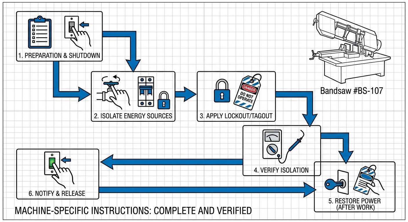
“This energy control procedure covers blade replacement, belt adjustment, and bearing lubrication on Bandsaw #BS-107 (Asset 2234-A), Building 3, Cell 7. Annual motor replacement requires Procedure ECP-2234-B.”
Not “turn off the machine.” The actual sequence.
What to include:
The authorized employee performing lockout needs enough detail to shut down equipment they may not operate daily.
This is where generic templates fall apart. “Isolate all energy sources” tells the worker nothing.
What to include for each energy source:
A maintenance technician should be able to walk to every isolation point using only this procedure. If they have to ask someone “which valve?”, the procedure fails.
Your procedure must specify what lockout hardware goes where.
“Lockout devices… shall be affixed to each energy isolating device by authorized employees.”
— 29 CFR 1910.147(d)(4)(i)
Shop Floor Translation: Each energy isolating device gets a lock. If the machine has four isolation points — a breaker, two valves, and a pneumatic disconnect — the procedure specifies four lock placements. Not “lock out all energy sources.” Four specific instructions for four specific locations.
What to include:
This section separates procedures that protect workers from procedures that just satisfy paperwork requirements. More on this in the stored energy section below.
What to include:
The “try start” requirement. Non-negotiable.
“Prior to starting work on machines or equipment that have been locked out or tagged out, the authorized employee shall verify that isolation and deenergization of the machine or equipment have been accomplished.”
— 29 CFR 1910.147(d)(6)
Shop Floor Translation: After lockout, attempt to start the machine using normal operating controls. Confirm nothing happens. This verification step must be documented in the procedure — not assumed.
What to include:
Here’s what separates adequate procedures from audit-proof procedures: energy magnitude documentation.
OSHA requires authorized employees to understand “the type and magnitude of the energy” for machines they lock out. Most templates check the “type” box with generic labels: electrical, hydraulic, pneumatic. They ignore magnitude entirely.
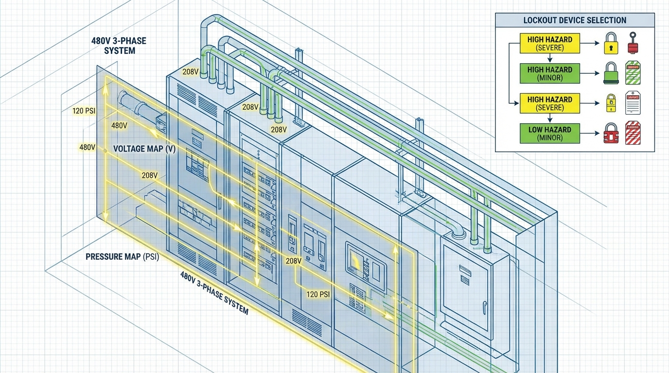
| Energy Type | Magnitude Documentation Required |
|---|---|
| Electrical | Voltage (480V 3-phase), amperage (60A), circuit designation |
| Hydraulic | Operating pressure (3000 PSI), accumulator pre-charge pressure |
| Pneumatic | Line pressure (120 PSI), receiver tank capacity (80 gallons) |
| Thermal | Operating temperature (450°F), cooldown time required |
| Gravitational | Component weight (2,400 lbs), drop height if blocking fails |
| Mechanical (springs) | Stored force (500 lb-ft), travel distance if released |
Why does this matter? Because magnitude determines hazard severity and influences lockout device selection. A worker locking out 480V needs different respect for the hazard than someone locking out 24V control circuits. Both need lockout. The consequences of failure differ dramatically.
Include magnitude in your energy control procedure template for:
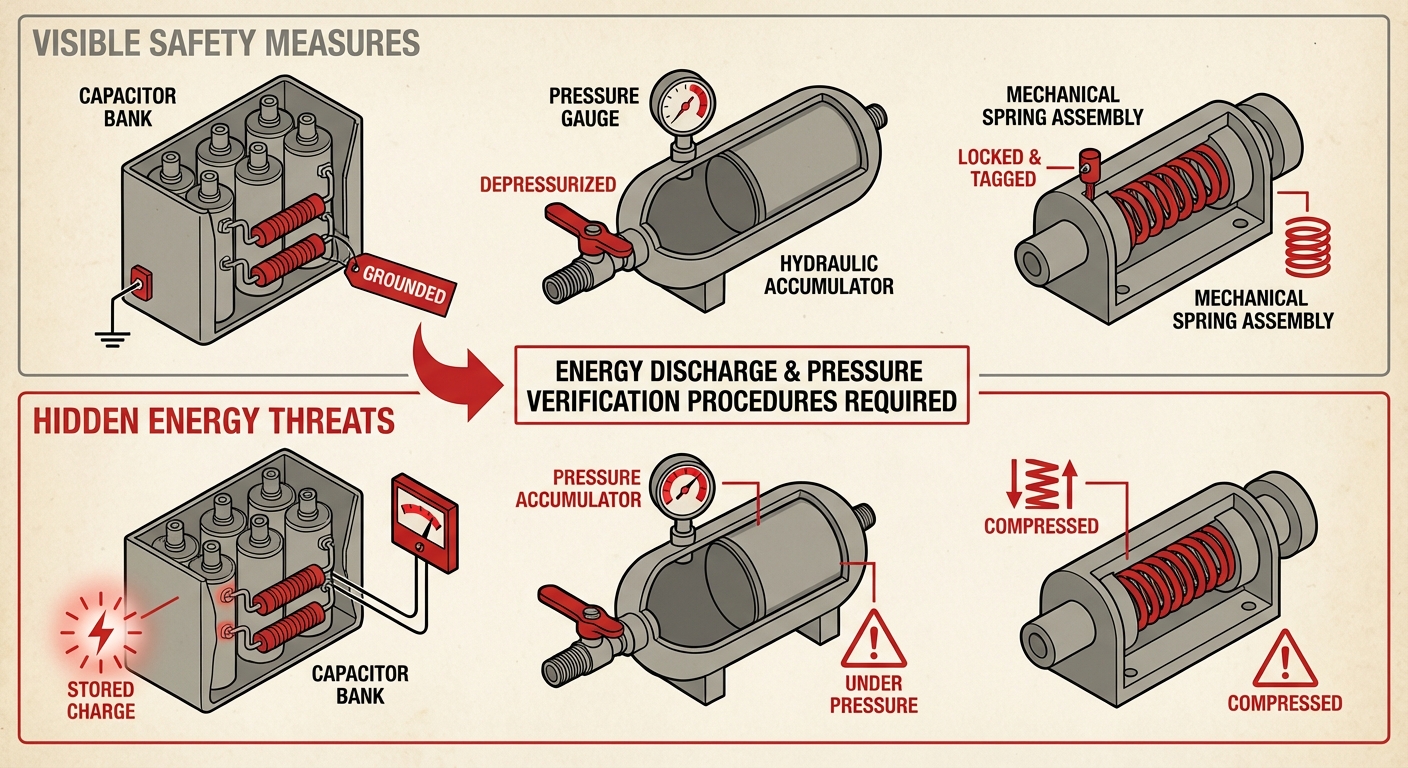
Stored energy violations hide inside “complete” procedures. The machine is locked out. Power is isolated. The authorized employee is cited anyway. Why?
Because residual energy remained in the system, the procedure didn’t address it, and someone got hurt — or an inspector noticed the gap.
“Following the application of lockout or tagout devices to energy isolating devices, all potentially hazardous stored or residual energy shall be relieved, disconnected, restrained, or otherwise rendered safe.”
— 29 CFR 1910.147(d)(5)(i)
Shop Floor Translation: Flipping the breaker off doesn’t eliminate the charge in capacitors. Closing the valve doesn’t eliminate pressure in the accumulator. Stored energy must be specifically addressed for each machine.
Capacitors retain charge after power isolation. Your energy control procedure template must include:
Failure pattern: “Allow capacitors to discharge” without specifying duration or verification. OSHA wants measured confirmation, not assumptions about dissipation time.
Compressed or extended springs store mechanical energy. If released unexpectedly, that energy goes somewhere — often into the worker.
What to include:
These are the most frequently missed stored energy sources. The hydraulic pump is off. Pressure remains in the accumulator.
What to include:
AUDIT TRAP: Your procedure says “bleed hydraulic pressure.” The inspector asks: “To what pressure level? How does the worker verify it?” If your answer is “until it stops” instead of “until gauge reads 0 PSI ±2 PSI,” prepare for the citation.
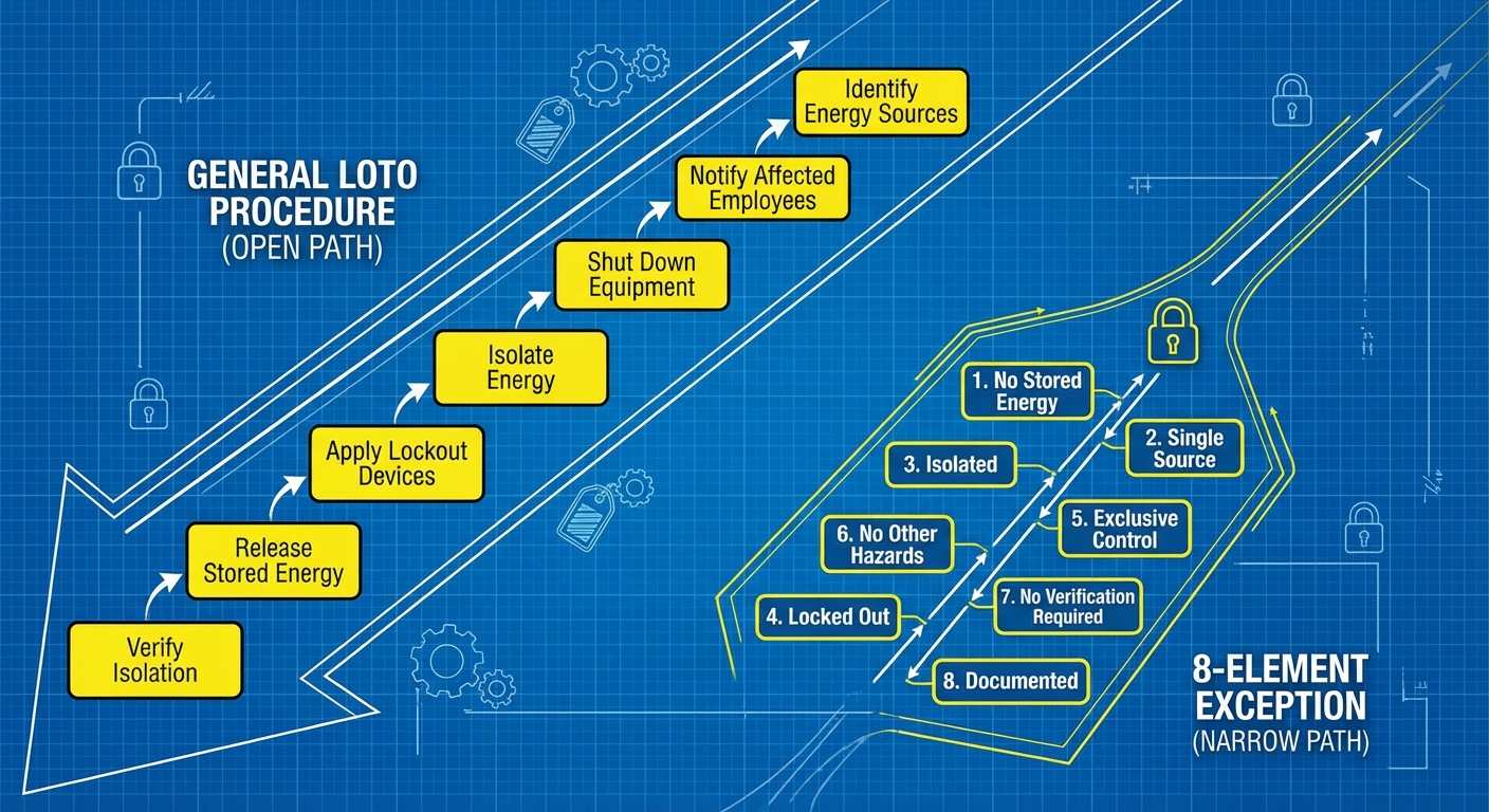
OSHA includes an exception at 1910.147(c)(4)(i) that allows skipping the written procedure. It’s narrow. It’s specific. And it disappears the moment you have an incident.
The exception applies ONLY when ALL eight conditions exist:
Miss one element, written procedure required. Have one near-miss incident, written procedure required permanently.
My recommendation: Write the procedure anyway. The exception requires you to verify eight conditions for every machine. That verification takes longer than writing the procedure. And when you have that first incident — and you will eventually — you’ll need the procedure regardless.
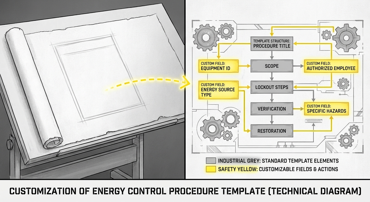
I’ve put together an energy control procedure template that includes all six OSHA-required sections plus the stored energy and magnitude documentation that separates citations from compliance.
This template includes:
The template is formatted for direct use. Fill in your machine-specific information. The structure ensures you don’t miss the sections that trigger citations.
[Download the Energy Control Procedure Template (Word .docx)]
Note: This template provides structure and required elements. You must customize it with machine-specific information for each piece of equipment requiring lockout/tagout.
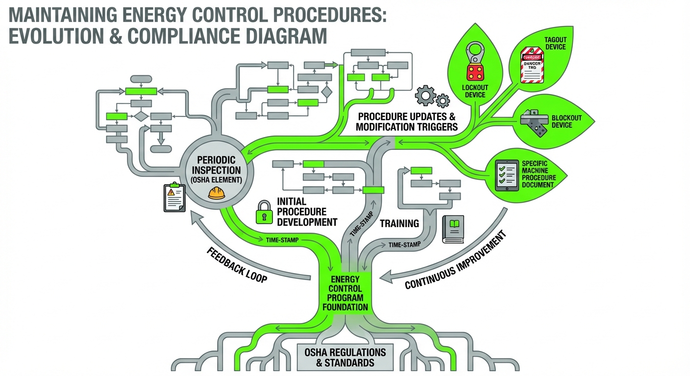
Documentation isn’t one-and-done. The regulation requires periodic inspection.
“The employer shall conduct a periodic inspection of the energy control procedure at least annually to ensure that the procedure and the requirements of this standard are being followed.”
— 29 CFR 1910.147(c)(6)(i)
Shop Floor Translation: Every energy control procedure needs annual inspection. Not annual training. Inspection means watching an authorized employee actually perform the procedure on the machine and verifying the documented steps match reality.
When machines are modified — new controls, relocated disconnects, additional energy sources — the procedure updates immediately. Annual inspection catches drift. Modification triggers immediate revision.
Q: Can I use one energy control procedure for multiple identical machines?
A: Only if they are truly identical in current configuration. Same make, model, and options don’t guarantee identical lockout requirements. Modifications, different panel locations, auxiliary equipment connections, and facility-specific installation differences require verification. Many facilities find separate procedures for “identical” machines easier to maintain than proving ongoing equivalence.
Q: What if my machine has more energy sources than the template allows?
A: Add rows. The template structure accommodates any number of energy sources. Complex machines with 8-10 isolation points need 8-10 documented lockout steps. Don’t compress multiple energy sources into single line items to fit a form — expand the form to match the machine.
Q: How specific does the location information need to be?
A: Specific enough that a qualified worker unfamiliar with the machine can locate every isolation point without asking for help. “Panel 3B, Breaker 17, north wall of Building 2, 15 feet east of Column J-7” beats “main electrical panel.” If someone has to hunt for it, the procedure isn’t specific enough.
Q: Does every piece of equipment need an energy control procedure?
A: Every piece requiring LOTO for servicing needs either a machine-specific written procedure or documented verification that it qualifies for the 8-element exception. Cord-and-plug equipment under exclusive control during servicing has a separate exception. When in doubt, write the procedure.
Q: Who should write the energy control procedure?
A: Someone who knows the machine. Typically maintenance supervision working with operators who run the equipment daily. The authorized employees who will use the procedure should review it before implementation. Outside consultants can provide templates and structure, but machine-specific knowledge comes from your people.